Shielding for Imaging Systems
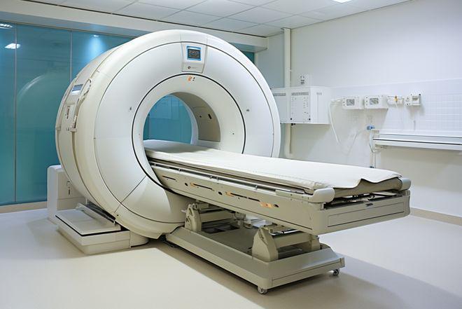
Diagnostic X-ray system shielding is covered by NCRP-147 and AAPM TG-108. The methodology used for shielding imaging systems shares many similarities with linac vault shielding and NCRP-151.
Downloads
NCRP Report 147: Structural Shielding Design for Medical X-ray Imaging Facilities (External Link, requires AAPM membership)
AAPM TG-108: PET and PET/CT Shielding Requirements (External Link)
Typical Shielding Requirements
| Room Type | Typical Shielding |
|---|---|
| High Energy Linear Accelerator Primary Barrier | 1.5-3m concrete |
| High Energy Linear Accelerator Secondary Barrier | 1-1.5m concrete |
| High Energy Linear Accelerator Door | With maze0.5 - 2cm inner lead layer2-4cm BPE1cm outer lead layerNo Maze5-9cm inner lead layer15-25cm BPE1cm outer lead layer |
| Ir-192 HDR Suite | ~50cm concrete |
| PET/CT Room | 1-2cm lead15-20cm concrete |
| CT Room | 1/16" to 1/8"Pb walls1/32" to 1/8" Pb ceiling and (possibly) floor |
| Radiographic Suite | Primary Barriers: 1/16"to 1/8"PbSecondary Barriers: 1/23"to 1/16" Pb |
CT Shielding (NCRP 147 Methodology)

- B is the maximum shielding transmission factor.
- P are the shielding design goals.
- d is the distance from the bore center to the point of interest.
- T is the occupancy factor.
- K1 is the air kerma per patient at a distance of 1 meter.
- N is the number of patients per week.
Note that there is no use factor for a CT scanner. This is because CT rooms have no primary barriers because of the image detectors attenuation of the beam.
Key Point: NCRP-147 specifies shielding design goals in air kerma rather than dose equivalent or effective dose. This is because air kerma is readily measurable and the relationship between air kerma and effective dose depends on a variety of factors including orientation and posture of the individual.

Determining the thickness of shielding material required to reach a given transmission factor is more complicated than in MV shielding calculations because the attenuation coefficients of materials vary strongly with energy spectrum for kV photons. The below equation gives the minimum required barrier thickness. α, β, and γ are fitting parameters for broad beam x-ray source attenuation of a given shielding material.
Lead photon attenuation. Source: NCRP-147 figure A.2.
Concrete photon attenuation. Source: NCRP-147 figure A.3.
Methods for determining Air Kerma per patient (K1)
CTDI100 Method
This method uses measured values of
CTDI100 and an empirically derived κ value to determine K1.

- P is the pitch
- L is the scan length
- κ is the scatter fraction per centimeter for head or body phantom
Dose Length Product (DLP) Method
Many modern CT scanners display dose-length-product (DLP) for their scans. This provides a simple approach to determining K1.

- κ is the scatter fraction per centimeter for head or body phantom
Isodose Map Method
The simplest method for determining
K1 is to simply use a vendor supplied isodose map for the scanner.
If using this technique, care must be taken to correct for differences in acquisition technique used to create the map such as slice thickness, mAs, and kVp.
PET/CT Shielding
Shielding of a PET/CT scanner is the topic of TG-108. TG-108 focuses on F-18 based PET scanning because it is the most common radionuclide used in PET imaging. Additionally, because of F-18’s relatively long half life (110 minutes), shielding calculations based on F-18 are also adequate for other, shorter-lived radionuclides such as O-15 (T1/2 = 2 minutes), N-13 (T1/2 = 10 minutes) and C-11 (T1/2 = 20.4 minutes).
Key point: Typical PET/CT shielding requirements will be dominated by the 511keV photons that result from positron-electron annihilation from the PET radionuclide.


- B is the maximum shielding transmission factor.
- P the shielding design goal.
- d is the distance from the center of the patient to the point of interest (m).
- T is the occupancy factor.
- NW is the number of patients per week.
- A0 is administered activity (MBq).
- tU and tI are the time in uptake room and time in imaging room respectively (hr).
- FU is the uptake decay factor.
- RtU and RtI are the dose reduction over uptake and imaging times.